Copyright © 2018-2019 J. Sérot ‐ All Rights Reserved
Last update : 2019/03/09

Copyright © 2018-2019 J. Sérot ‐ All Rights Reserved
Last update : 2019/03/09
Finally, hitting the , and buttons will generate respectively
-an implementation of the model in a C dialect (with dedicated types and primitives for events),
-an implementation of the model and testbench in SystemC
-an implementation of the model and testbench and VHDL
More examples can be found on the Examples page.
About RFSM
RFSM is a set of tools aimed at describing, drawing and simulating reactive finite state machines (FSMs). Reactive FSMs are a FSMs for which transitions can only take place at the occurence of events.
RFSM has been developed mainly for pedagogical purposes, in order to initiate students to model-based design. It is currently used in courses dedicated to embedded system design both on software and hardware platforms (microcontrolers and FPGA resp.). But RFSM can also be used to generate code (C, SystemC or VHDL) from high-level models to be integrated to existing applications.
RFSM is actually composed of three distinct tools :
-a command-line compiler (rfsmc)
-a graphical user-interface (GUI) to the compiler
-a library for the OCaml programming language
These tools can be used to
-describe FSM-based models and testbenches
-generate graphical representations of these models (.dot format) for visualisation
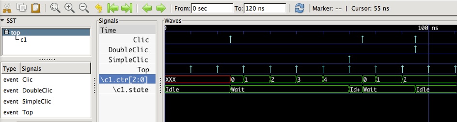
-simulate these models, producing .vcd files to be displayed with waveform viewers such as gtkwave
-generate C, SystemC and VHDL implementations (including testbenches for simulation)
RFSM
Reactive Finite State Machines
At a glance
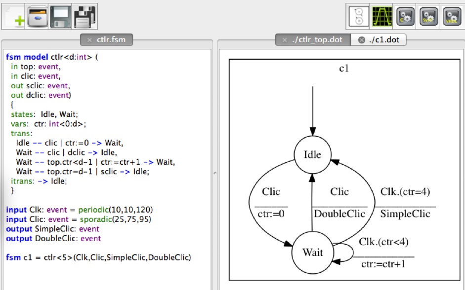
Below is a screen copy showing the GUI in action on a very simple design : a simplified mouse controler. The controler has two inputs, Top and Clic, and two outputs SimpleClic and DoubleClic. The input Top provides a time base : an event is supposed to occur on this input every T ms. Whenever an event occurs on input Clic it emits an event on output DoubleClic or SimpleClic depending on whether this input event is followed by another one in a period P=D.T.
The left tab (ctlr.fsm) contains the design description, structured in three part : the FSM model itself (fsm model), a description of global inputs and outputs, with the stimuli attached to inputs and the instanciation of the FSM model (fsm c1). The FSM model is composed of declarations of parameters (D), inputs, outputs, local variables and states and a description of its behavior as a set of transition rules (trans). Each transition rules is of the form src--cond|acts-->dst where src and dst are the source and destination states, cond the condition enabling the transition (event + guard) and acts a sequence of actions. This model is instanciated at the last line by providing an actual value for parameter D (5 here) and bindings for its inputs and outputs. For the inputs, the attached stimuli are here specified as periodic for Top and sporadic for Clic.
The right tab shows the graphical description corresponding to the instanciated model. This description was obtained by clicking on the button.


Simulation of this design can be performed by hitting the button. If the application has been correctly configured, this will launch the gtkwave program for viewing the resulting traces, as shown below :